Hydro power plants maintenance
The reduction of failures, breakdowns, inefficiencies and unplanned outages is achieved through monitoring, control, diagnosis and condition assessment, periodically applying the most appropriate techniques to the main equipment of the plant, the deterioration or failure of which has a direct impact on operating income and derived costs.
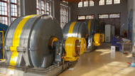
Vibrations and pulsations of the unit


Vibrations are result of cyclic forces linked to turbine-generator operation, the elements of the same react against each other, so that part of the energy is dissipated in the form of vibrations.
During its operation, the hydroelectric unit is subjected to the action of disturbing forces of mechanical, hydraulic and electrical origin; the identification and evaluation of the pulsations and vibrations present in the unit, separating those that are proper to its operation from those that have their origin in the anomalous operation of any of its elements, is carried out through the study and analysis of these vibrations and pulsations.
During its operation, the hydroelectric unit is subjected to the action of disturbing forces of mechanical, hydraulic and electrical origin; the identification and evaluation of the pulsations and vibrations present in the unit, separating those that are proper to its operation from those that have their origin in the anomalous operation of any of its elements, is carried out through the study and analysis of these vibrations and pulsations.
Detectable problems
- Unbalances: mechanical, hydraulic and electrical.
- Misalignment: angular and parallel.
- Mechanical looseness
- Dry friction
- Vortex ropes
- Cavitation
- Kármán vortex street
- Oil film instability
- Rotor-stator interactions
- Poles displacement
- Air gap variation
- Structural resonances
Standards
- IEC 60994
- ISO 7919
- ISO 10186
Equipment to measure
- Turbine (bearings in radial and axial direction and shaft in radial direction).
- Generator (bearings in radial and axial direction).
- Speed multiplier (bearings in radial and axial direction).
Measurements to be carried out
- Global RMS vibrations in high and low frequency of absolute bearing vibrations.
- Amplitude-frequency spectra, phase-frequency and cepstrum analysis of absolute bearing and relative shaft vibrations.
- Temporary wave of displacement in radial direction of the shaft in the turbine bearing.
Main measuring equipment
- Piezoelectric accelerometers.
- Eddy current probes.
- Dynamic signal analyzer (DSA).
Generator insulation
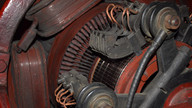


The assessment and diagnosis of the insulation status of the generator is carried out by periodically measuring the value of the insulation resistance and associated parameters. The extensive database and accumulated experience of this technique makes it, together with vibration-pulsation and thermography, the most reliable for the prevention of unexpected generator failures.
The evaluation factors depend on the type of material in the insulation system: thermosetting (epoxy or polyester) or thermoplastic (asphaltic).
The evaluation factors depend on the type of material in the insulation system: thermosetting (epoxy or polyester) or thermoplastic (asphaltic).
Standards
- IEEE 43
- IEEE 56
- IEEE 95
- IEEE 118
Equipment to measure
- Generator stator
- Generator rotor
Measurements to be carried out
- Insulation resistance corrected to 40º C (RC), at three different voltages.
- Insulation resistance curve as a function of time (IRP).
- Polarization index (PI).
- Dielectric absorption ratio (DAR).
- Dielectric discharge coefficient (DD).
- Time constant (τ10).
- High and low frequency capacity (C).
- Temperature difference (ΔT).
- Ohmic resistance corrected to 40º C (Rt).
Main measuring equipment
- Insulation meter (up to 15.000 Vdc).
- Microohmmeter.
- LCR meter.
- High resolution thermographic camera.
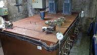
Transformer diagnostics
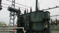


The transformer insulation system uses liquid insulation (mineral oil or silicone) and solid insulation (cellulose paper). The presence of an internal failure of the transformer, thermal or electrical origin, causes decomposition gases that dissolve in the insulating liquid. Using the dissolved gas analysis (DGA) technique, using the four combinations of relative percentage of only two gases, both the type of defect and its evaluation are determined, with which the condition of the transformer is diagnosed.
The assessment of the insulating liquid condition is carried out by means of physicochemical analysis applying the criteria according to the transformer category (O, A, B, C, D and E).
The assessment of the insulating liquid condition is carried out by means of physicochemical analysis applying the criteria according to the transformer category (O, A, B, C, D and E).
Standards
- ASTM D-1500
- IEC 60156
- IEC 60247
- IEC 60422
- IEC 60567
- IEC 60599
- IEC 60814
- UNE EN 62021
Equipment to measure
- Main power transformer
- Auxiliary services transformer
Measurements to be carried out
- Physical-chemical analysis of dielectric insulator (mineral oil or silicone).
- Appearance.
- Colour.
- Water content.
- Breakdown voltage.
- Index of acidity.
- Dissipation factor (tan δ).
- Particle content.
- Dissolved Gas Analysis (DGA).
- Hydrogen.
- Methane.
- Ethane.
- Ethylene.
- Acetylene.
- Atmospheric gases.
- Condition of the insulating paper.
- Temperature distribution.
Lubrication and hydraulic oils


The goal of lubricating oils is to reduce friction and wear between two surfaces that move relative to each other, additionally serve to dissipate heat, prevent corrosion and the entry of contaminants into surfaces.
Periodic analysis of lubricating and regulating oils makes it possible to verify the condition of the oils and quantify the effect of oxidation on them, this is their degradation; also serves to determine both the type and quantity of contaminants in the oil due to the existence of problems (contamination, wear and shaft-bearing friction) in lubrication and regulation systems.
Periodic analysis of lubricating and regulating oils makes it possible to verify the condition of the oils and quantify the effect of oxidation on them, this is their degradation; also serves to determine both the type and quantity of contaminants in the oil due to the existence of problems (contamination, wear and shaft-bearing friction) in lubrication and regulation systems.
Standards
- ASTM D-445
- ASTM D-664
- ASTM D-5185
- ASTM D-6304
- ASTM E-2412
- ASTM E-2412/10
Equipment to measure
- Bearing lubrication systems.
- Gear lubrication systems.
- Turbine regulation system.
Measurements to be carried out
- Physicochemical analysis.
- Appearance .
- Kinematic viscosity at 40º C.
- Oxidation.
- Nitration.
- Acidity (TAN).
- Water content.
- Additives (Mg, Zn, P, Ca, Li, B).
- Wear and contamination metals (Fe, Cr, Ni, Al, Cu, Sn, Pb, Si, Mo, Na).
- Particle Quantification Index (PQI).
Infrared thermography
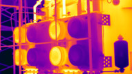


Infrared thermography allows to obtain a direct image of the temperature distribution of both mechanical and electrical equipment in operation; alerting of anomalous temperature increases due to the existence of specific problems prior to the failure.
As it's a contactless measurement, thermographic inspection is carried out safely and is therefore suitable for monitoring live electrical equipment, especially balanced three-phase systems and mechanical in relative movement.
As it's a contactless measurement, thermographic inspection is carried out safely and is therefore suitable for monitoring live electrical equipment, especially balanced three-phase systems and mechanical in relative movement.
Detectable problems
- Unbalanced three-phase systems.
- Improper screw torques.
- Cooling ducts clogged.
- Failures in transformers, fuses and batteries.
- Inefficiency in heating systems.
- Anomalous heating in components.
- Overload on bearings.
Equipment to measure
- Turbine-generator unit.
- Power transformers.
- Measuring transformers.
- Switches and batteries.
- Line output.
- Pumps and motors.
Main measuring equipment
- High resolution thermographic camera.
- Amperimetric clamp.
- Power Quality Analyzer.